Integrating the Hardware
What you will need
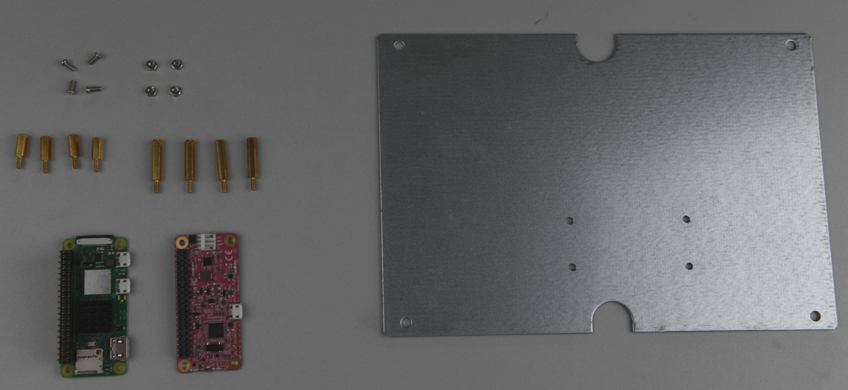
Required tools & components
- Soldering Iron (+ Solder) or Hammer Header
- Pliers
- 6x Cable Tie Mount
- 6x Stainless Steel Cable Ties
- 1x releasable Cable Tie
- Silica Gel Pack 50 g
- OAK-1 (OpenCV AI Kit)
- Raspberry Pi Zero 2 W (+ microSD card)
- RPi CPU Heatsink
- RPi Header
- RPi Stacking Header
- RPi Spacer Bolts 10 mm
- RPi Spacer Bolts 20 mm
- PiJuice Zero UPS pHAT
- Solar Panel Extension Cable, 1 ft
- Voltaic 12,800mAh Li-Ion Battery (Full Setup only)
- 2x Thermal Pad (1 mm) 50x50 mm (optional)
- 2x Heatsink 40x30 mm (optional)
- Solar Panel Micro USB Adapter
- PiJuice 12,000mAh LiPo Battery
- Micro USB to USB A Adapter, angled
- USB A to micro USB cable, 20 cm, angled (Full Setup only)
- Solar Panel 6V 9W
OAK-1 and silica gel fixing
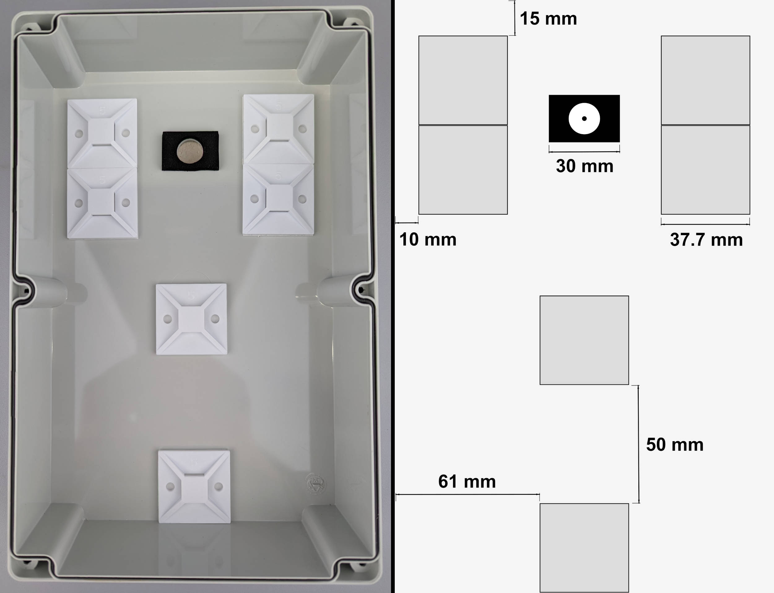
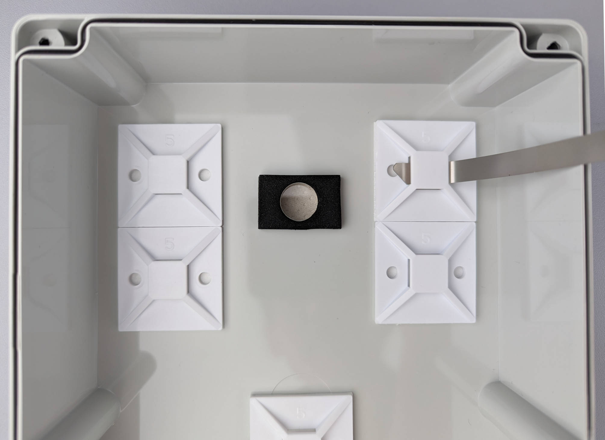
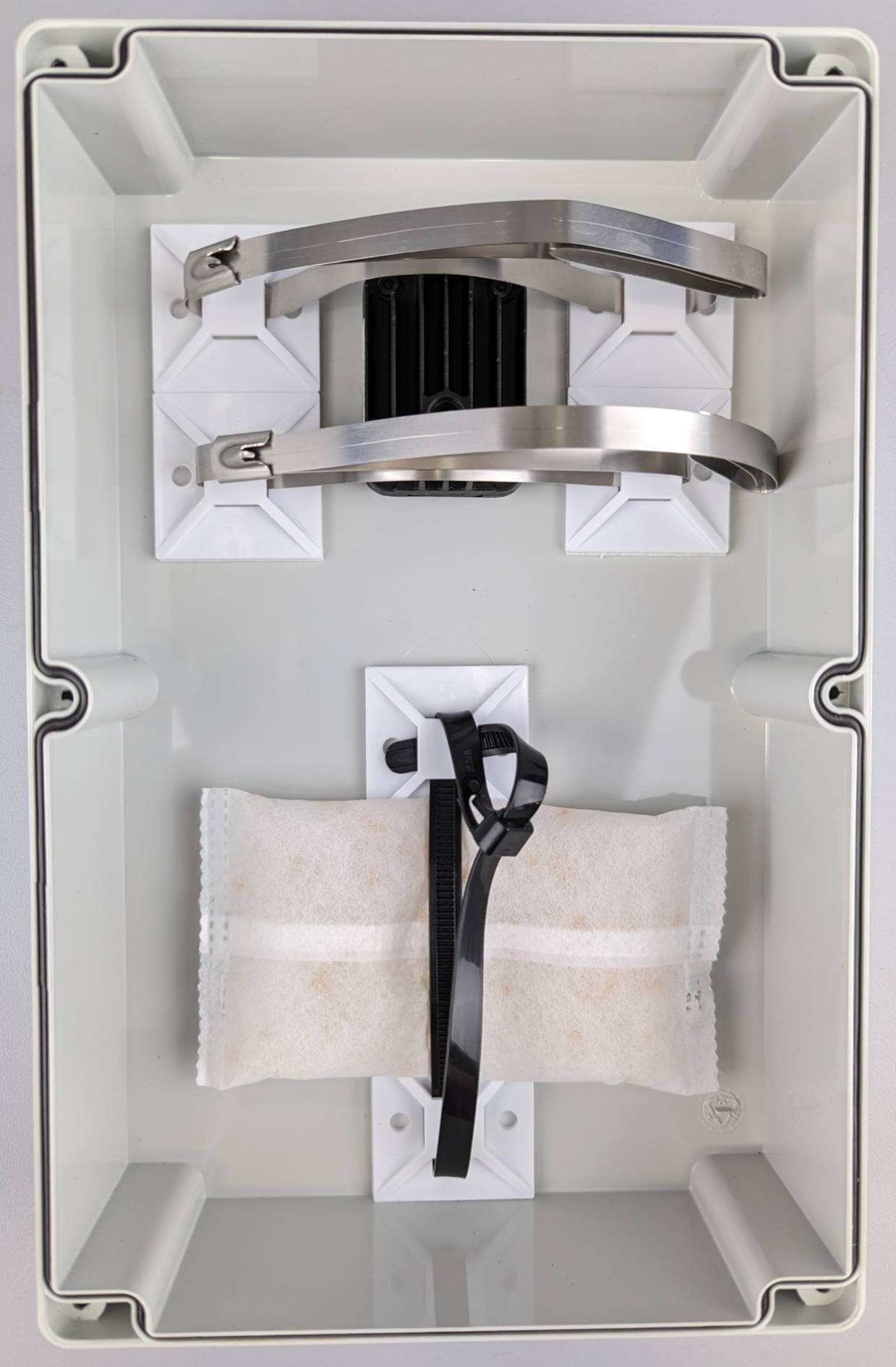
As we just finished preparing the lid of the enclosure, we can continue with sticking the cable tie mounts to the inside of the lid to attach the OAK-1 and a pack of silica gel. Clean the surface with some alcohol and mark the positions of the cable tie mounts before attaching them.
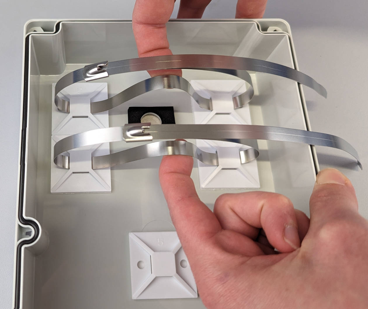
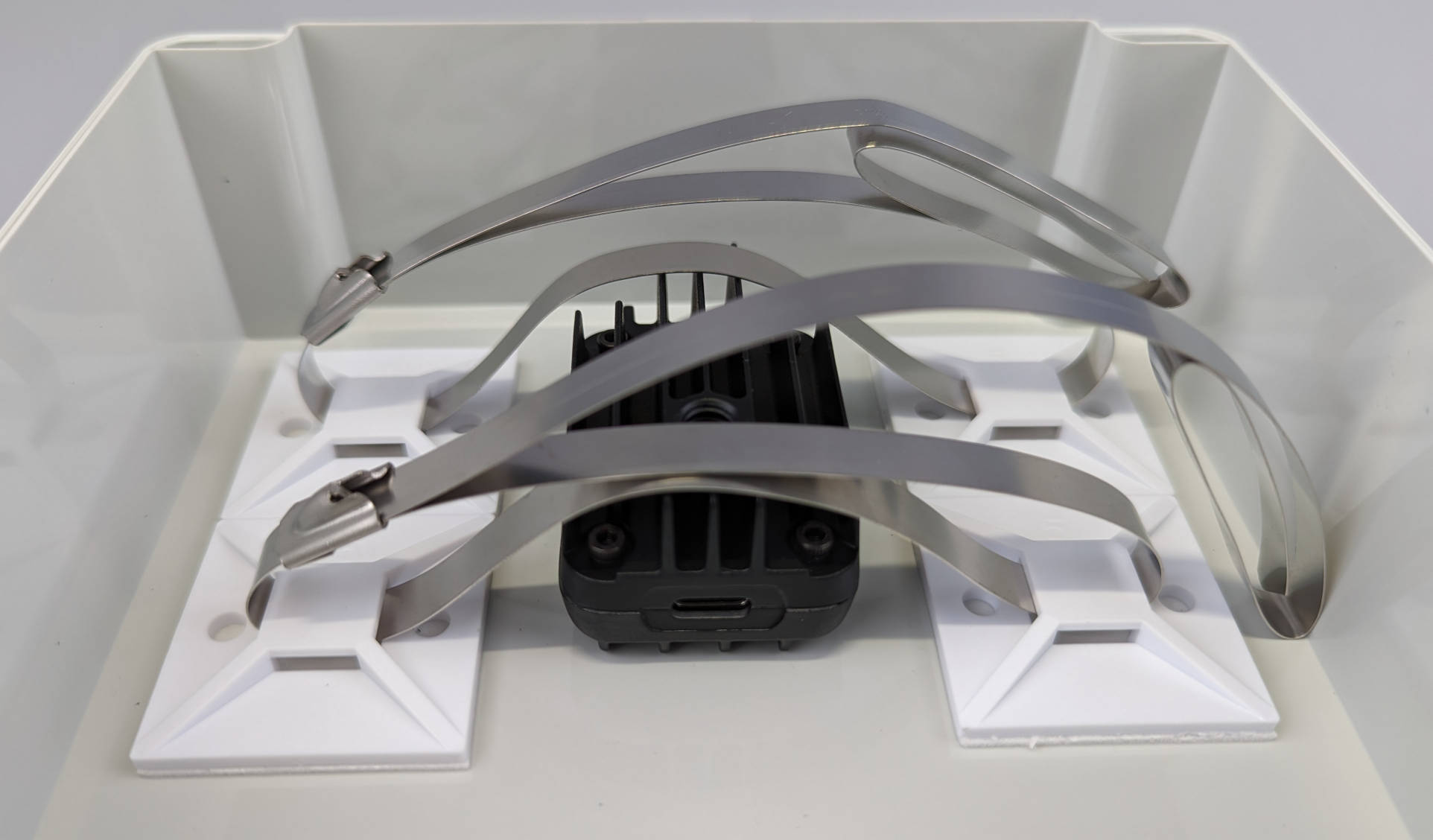
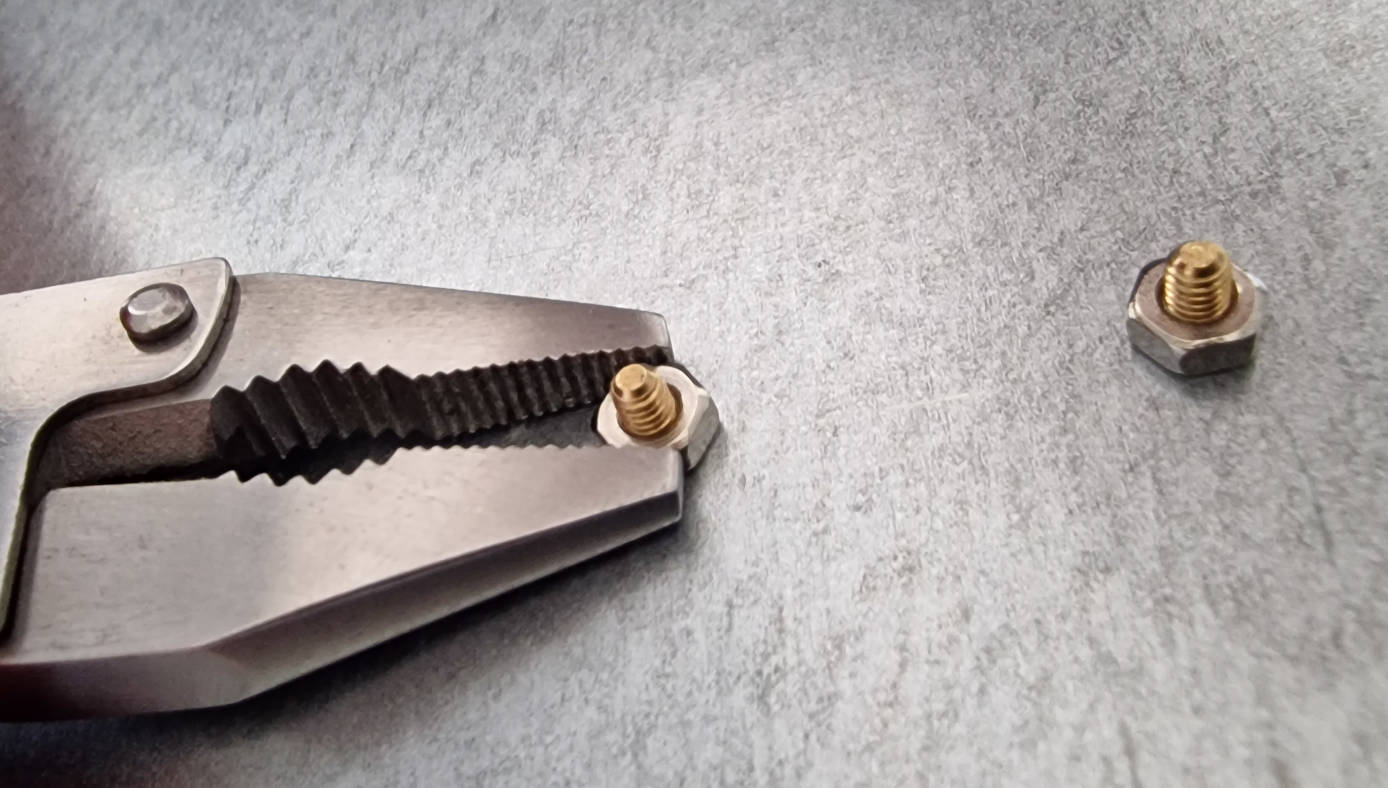
Now we are going to put the stainless steel cable ties through the cable tie mounts after bending the tip of the cable ties a little bit.
After attaching and connecting the cable ties, bend them a litte bit to make it easier to put the OAK-1 under them in the next step.
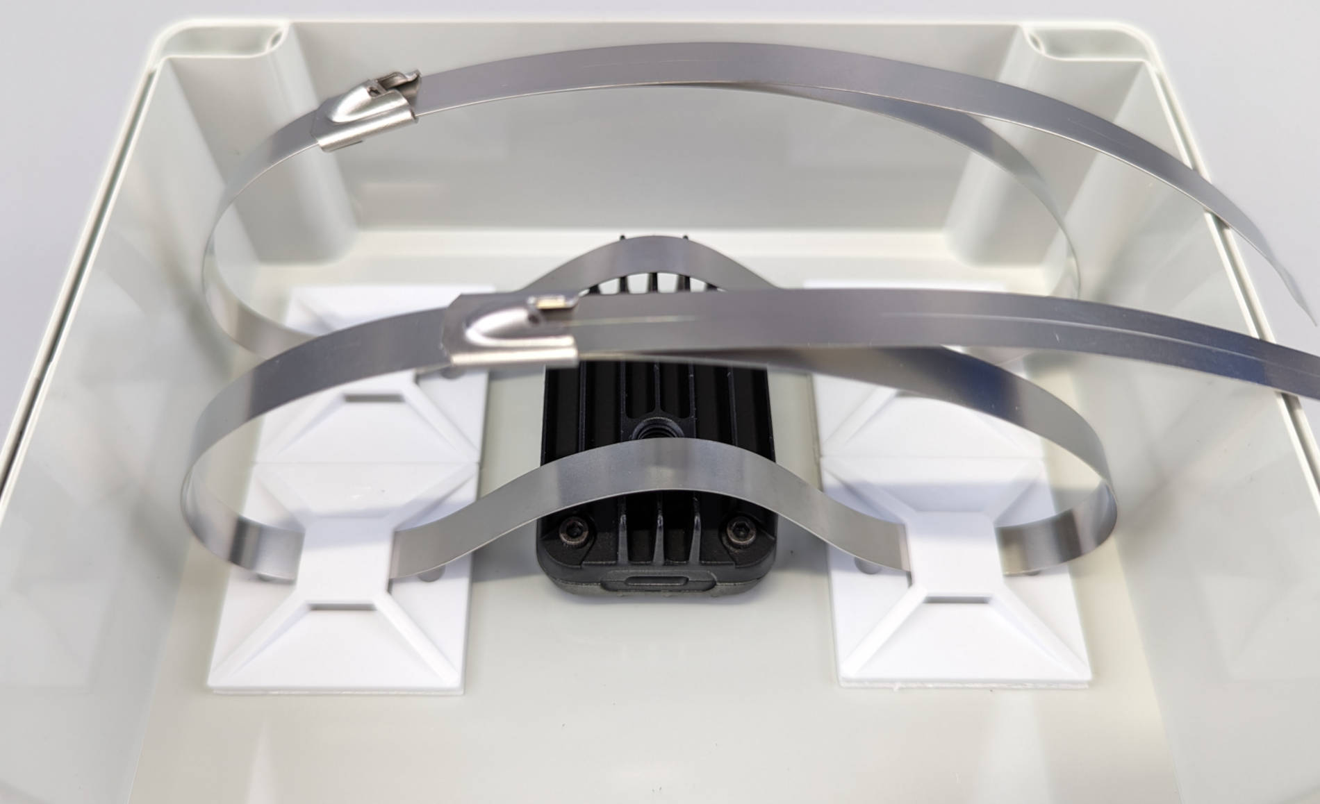
Make sure to center the lens of the OAK-1 camera before you tighten the cable ties.
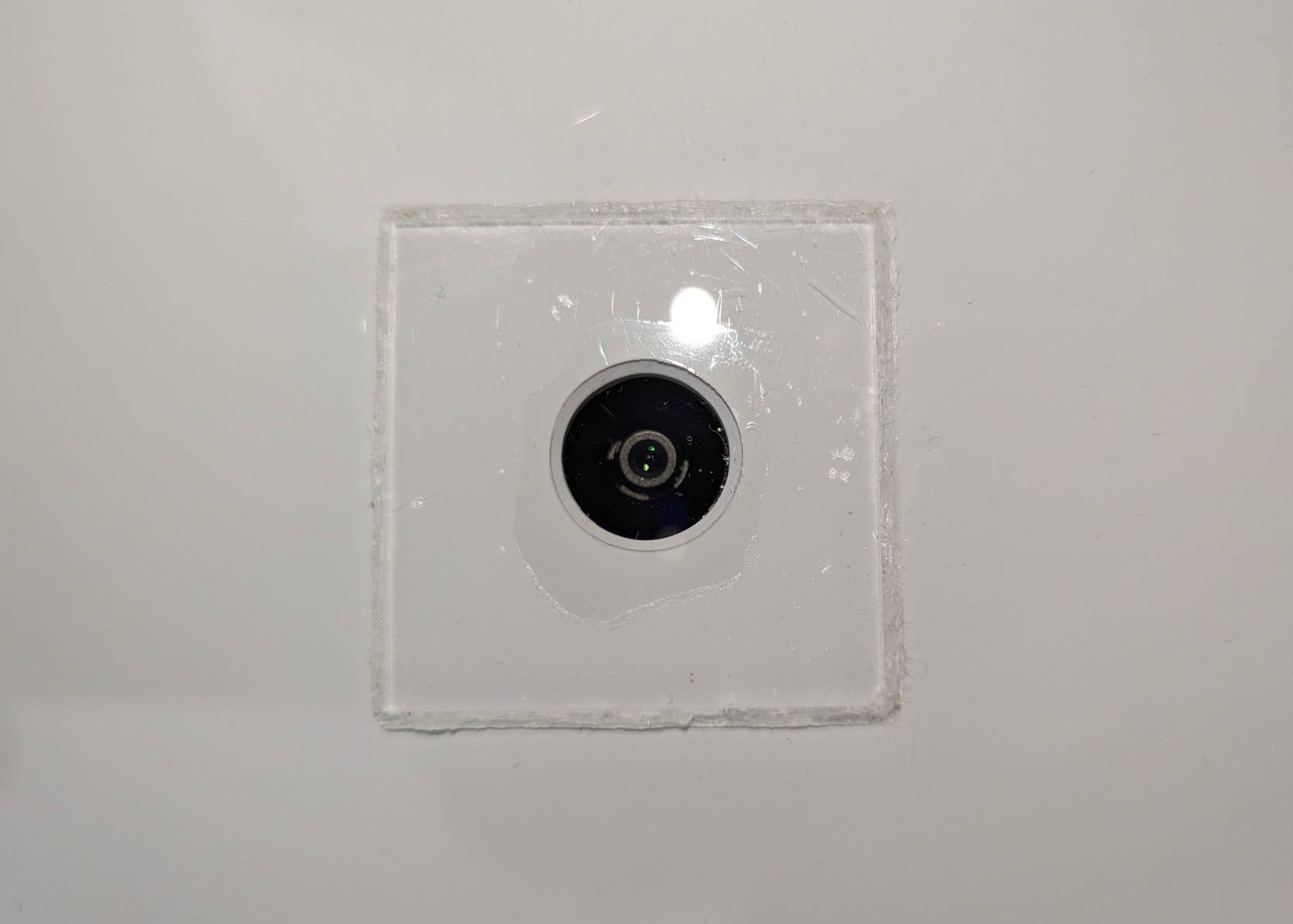
If you used the suggested 52 cm long steel cable ties, cut off or bend the protruding ends after tightening.
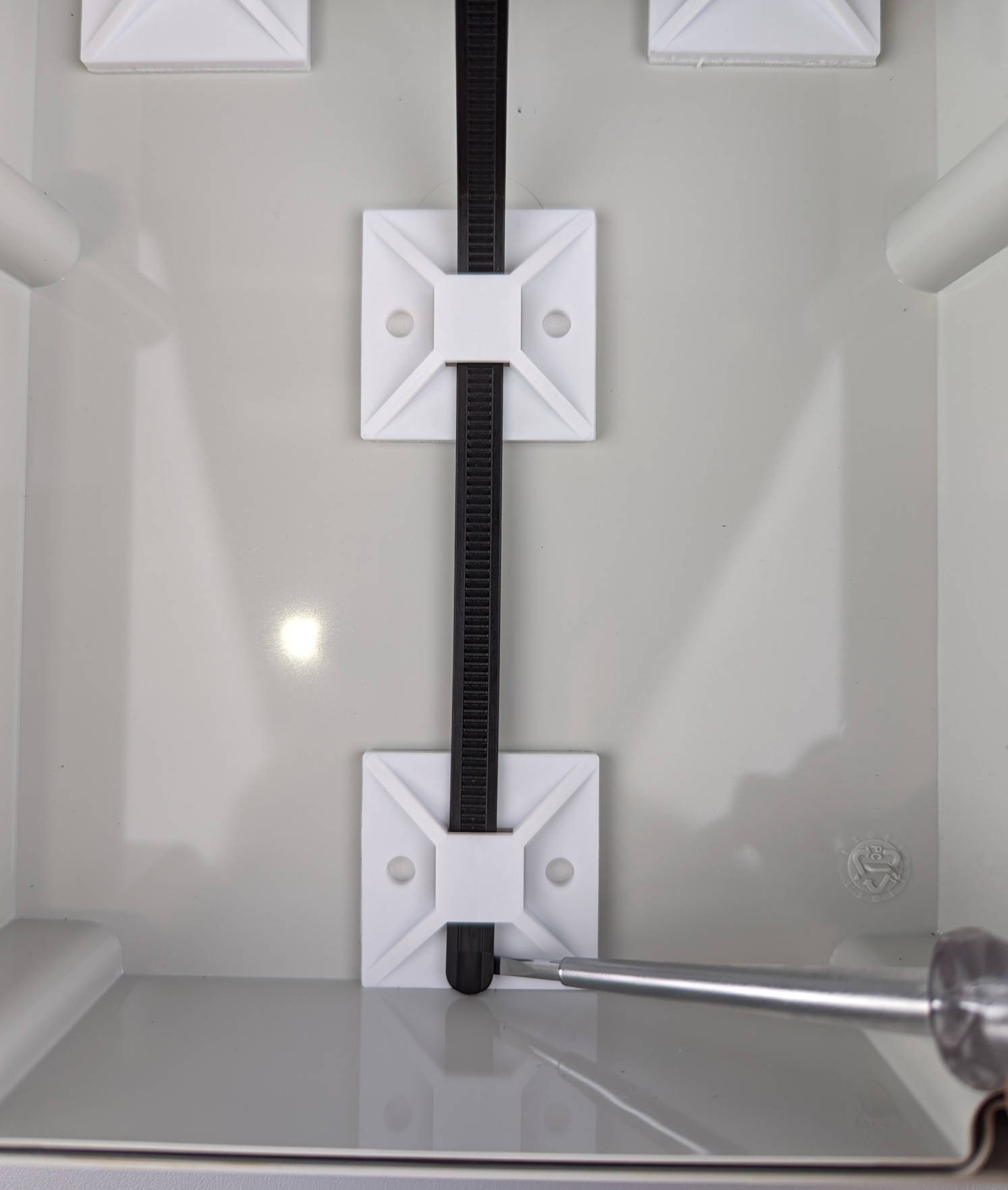
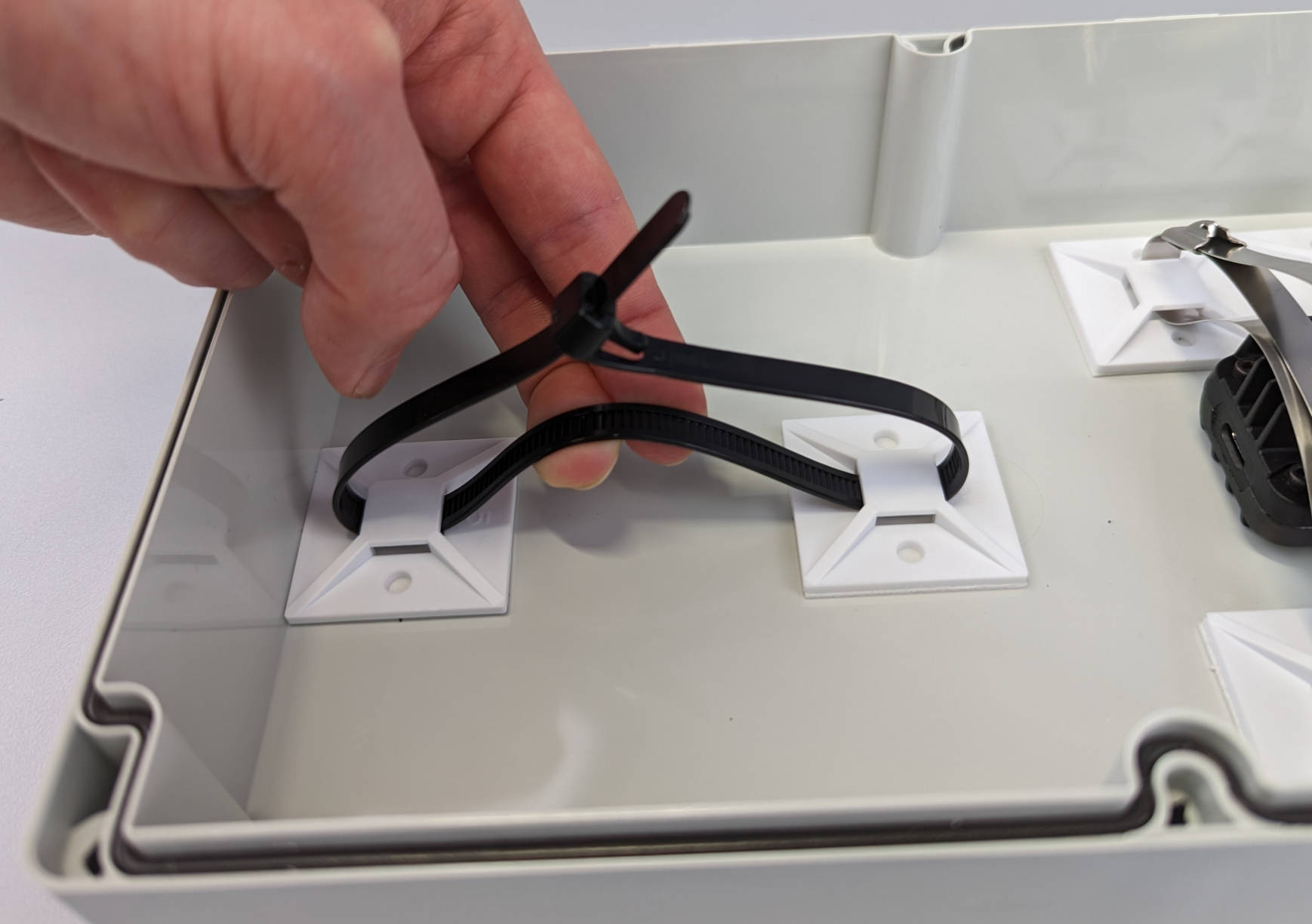
While you could also use one of the stainless steel cable ties to fix the silica gel pack, we will use a shorter releasable plastic cable tie to make exchanging of the silica pack easier. Raise the end of the cable tie with e.g. a screwdriver if it does not bend when touching the side of the lid.
Connect the cable tie loosely and bend it to put the silica gel pack underneath.
The lid of the enclosure is finished now and we are going to move on with attaching the rest of the hardware to the mounting plate of the enclosure.
RPi and PiJuice fixing
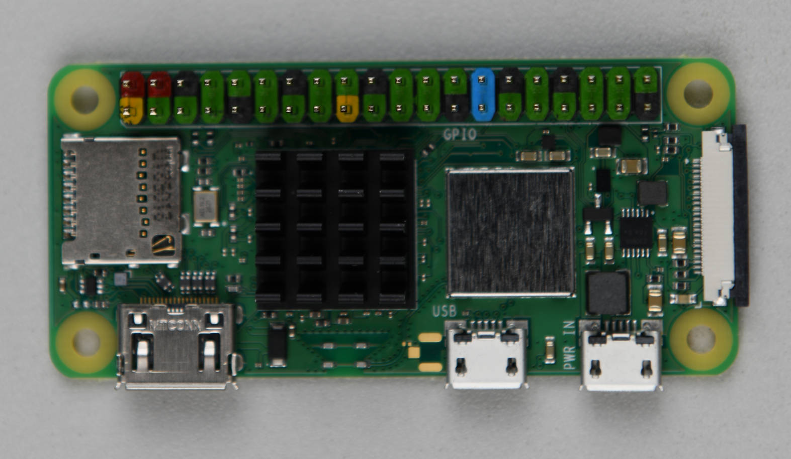
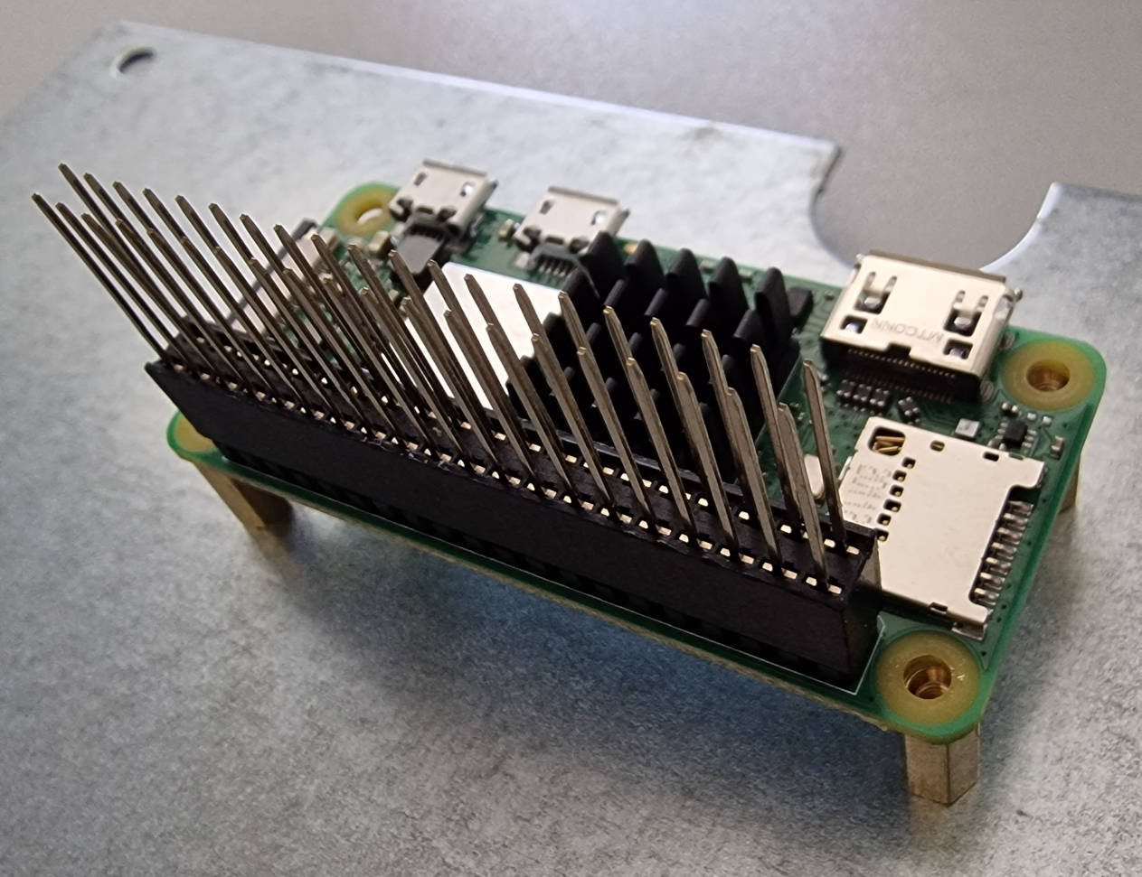
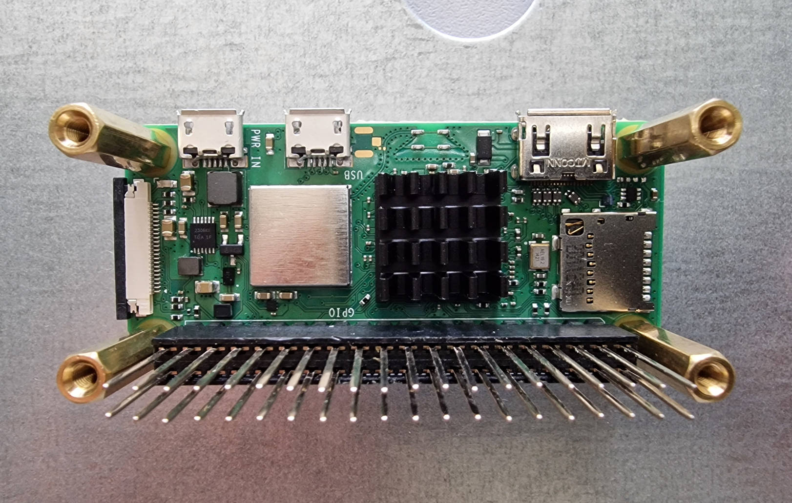
If you don't already have a Raspberry Pi Zero 2 W with attached header, you will have to solder a header to it. Before doing that, make sure to stick the heatsink on the CPU of your Raspberry. This will keep the header sitting flush against the Raspberry Pi as you solder it. If this is your first time soldering, you can find detailed instructions here. As alternative to soldering the header, you could also use a Hammer Header.
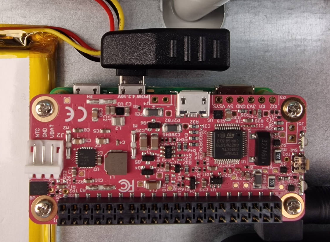
After attaching the CPU heatsink and soldering or hammering the header, your Raspberry Pi should look like this:
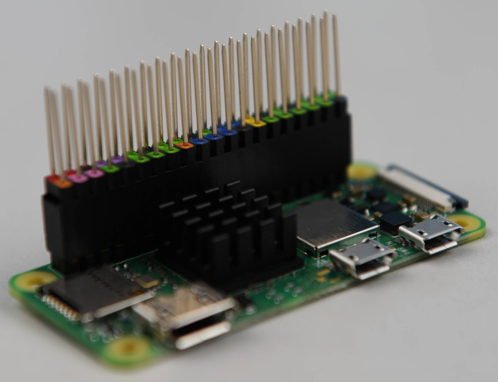
Now we can put the stacking header on top of the freshly soldered header.
The Raspberry Pi is now prepared to be attached to the mounting plate together with the PiJuice Zero pHAT. For this, we will need the 10 mm and 20 mm spacer bolts, as well as the four screws and nuts that came with the bolts.
We are going to put the smaller 10 mm spacer bolts into the four holes we previously drilled.
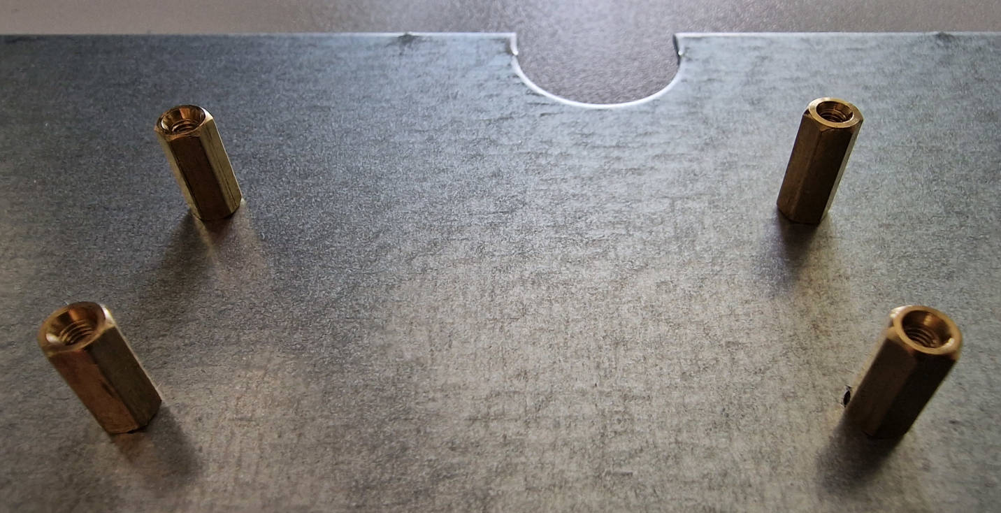
Then fasten the bolts with the nuts at the backside of the mounting plate. But don't tighten them yet! We will need a little bit of space to align the components on the other side of the mounting plate in the following steps.
Place your Raspberry Pi on top of the spacer bolts. Make sure that the ports are pointing towards the edge of the mounting plate.
You can now screw the longer 20 mm spacer bolts into the 10 mm bolts to fix the Raspberry Pi to the mounting plate. Don't tighten too much as we will need some space to align everything later.
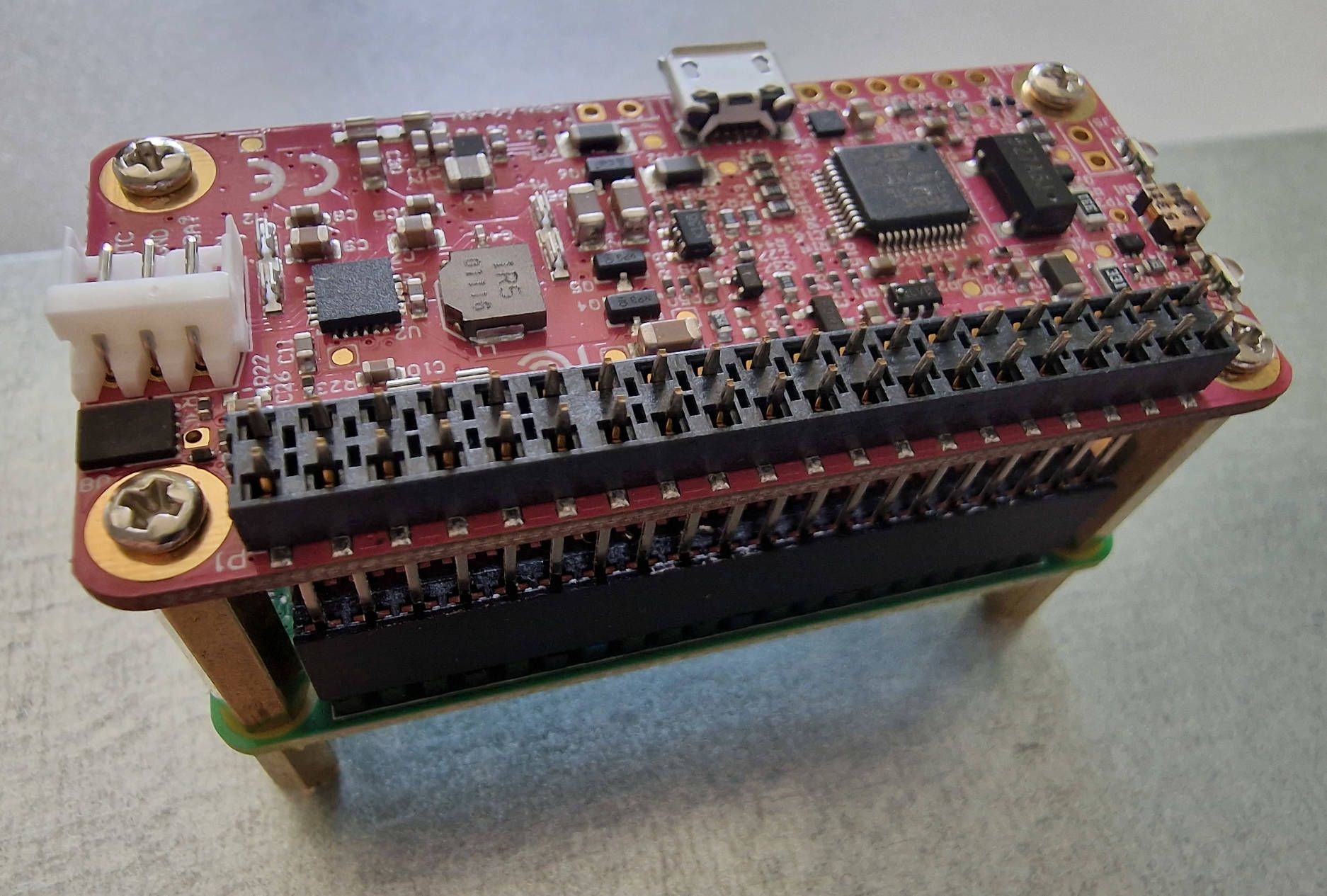
In the last step, connect the PiJuice Zero pHAT to the GPIO pins of the RPi stacking header. If you have trouble with this, you can check if some of the pins are not properly aligned and adjust them carefully before trying again. Finally, fasten the screws on top of the PiJuice board and properly tighten all bolts and the nuts on the backside of the mounting plate.
Inserting the mounting plate
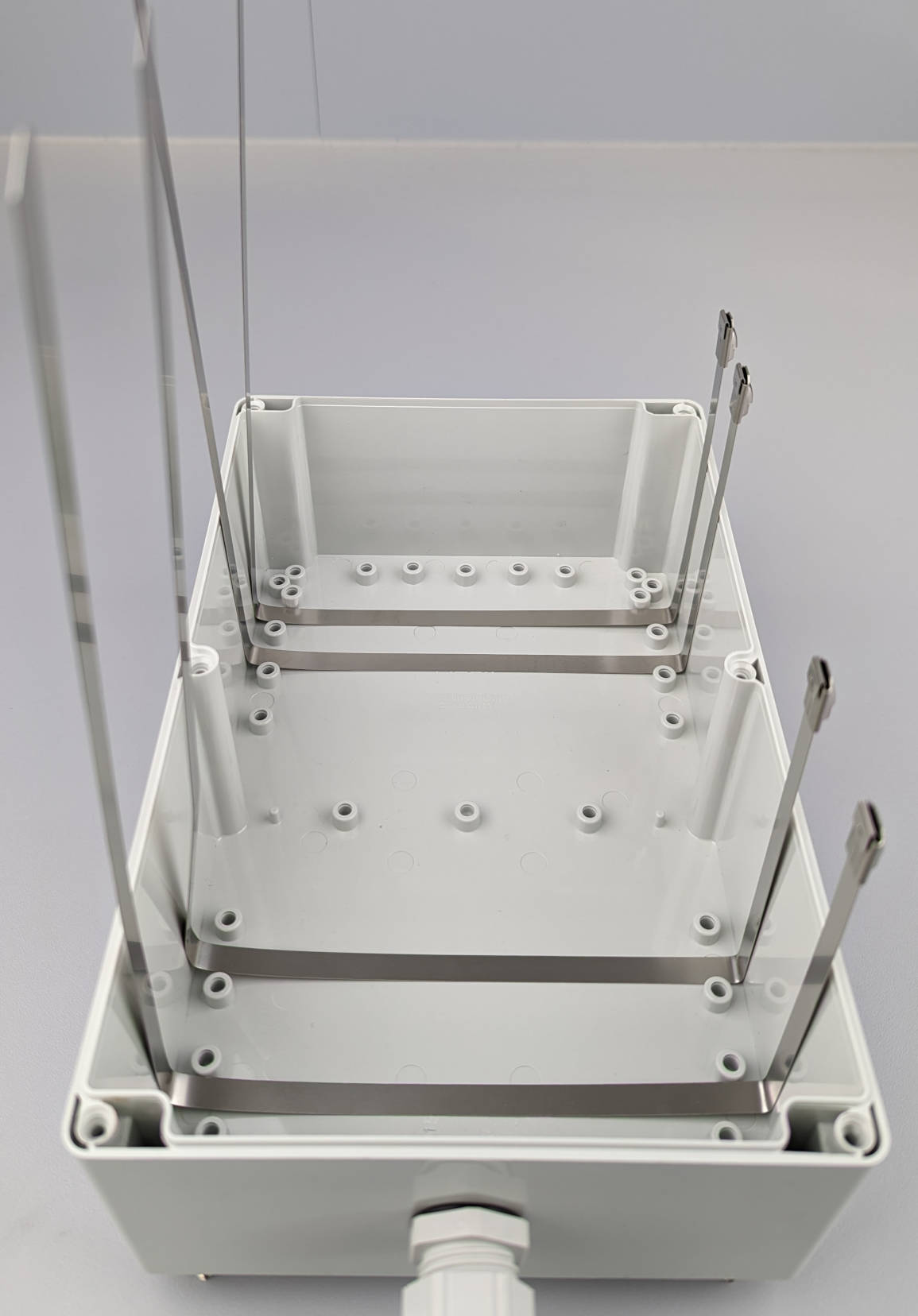
Before inserting the mounting plate into the enclosure, the four cable ties have to be aligned with the positions where the batteries will be. If you only have shorter cable ties, you can connect two ties for extension. Bend the cable ties at 12 cm, measured from the head of the cable tie (right side in image). Put them into the enclosure, between the mounting threads as shown in the following image, and bend the cable ties at the other side of the enclosure bottom.
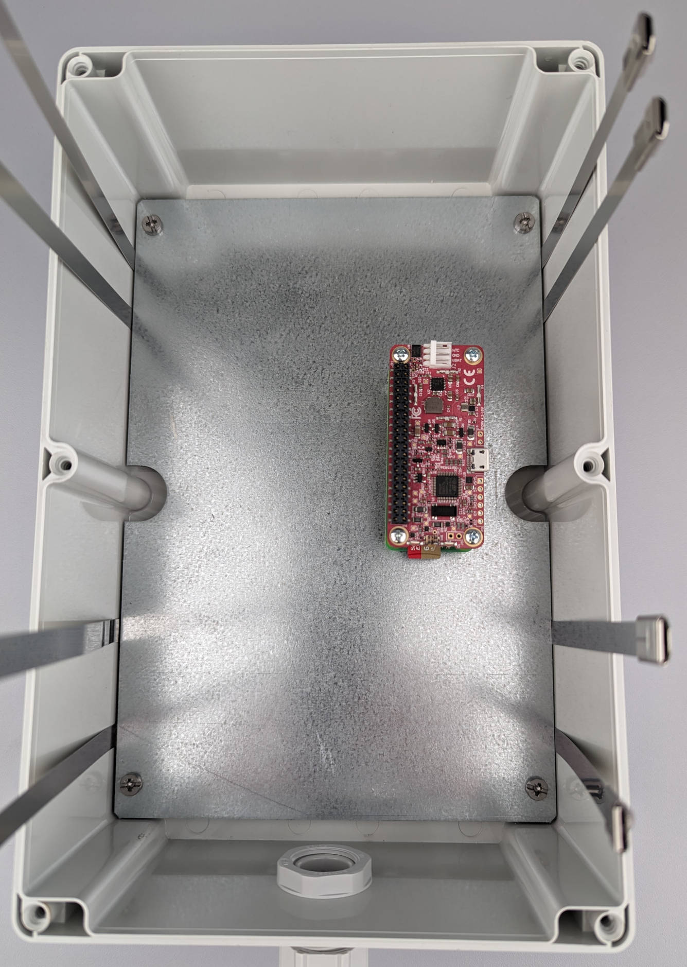
Insert the mounting plate into the enclosure while keeping the cable ties in position. Screw the plate to the enclosure with the included screws.
Integrating the batteries
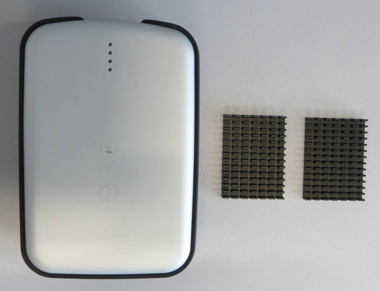
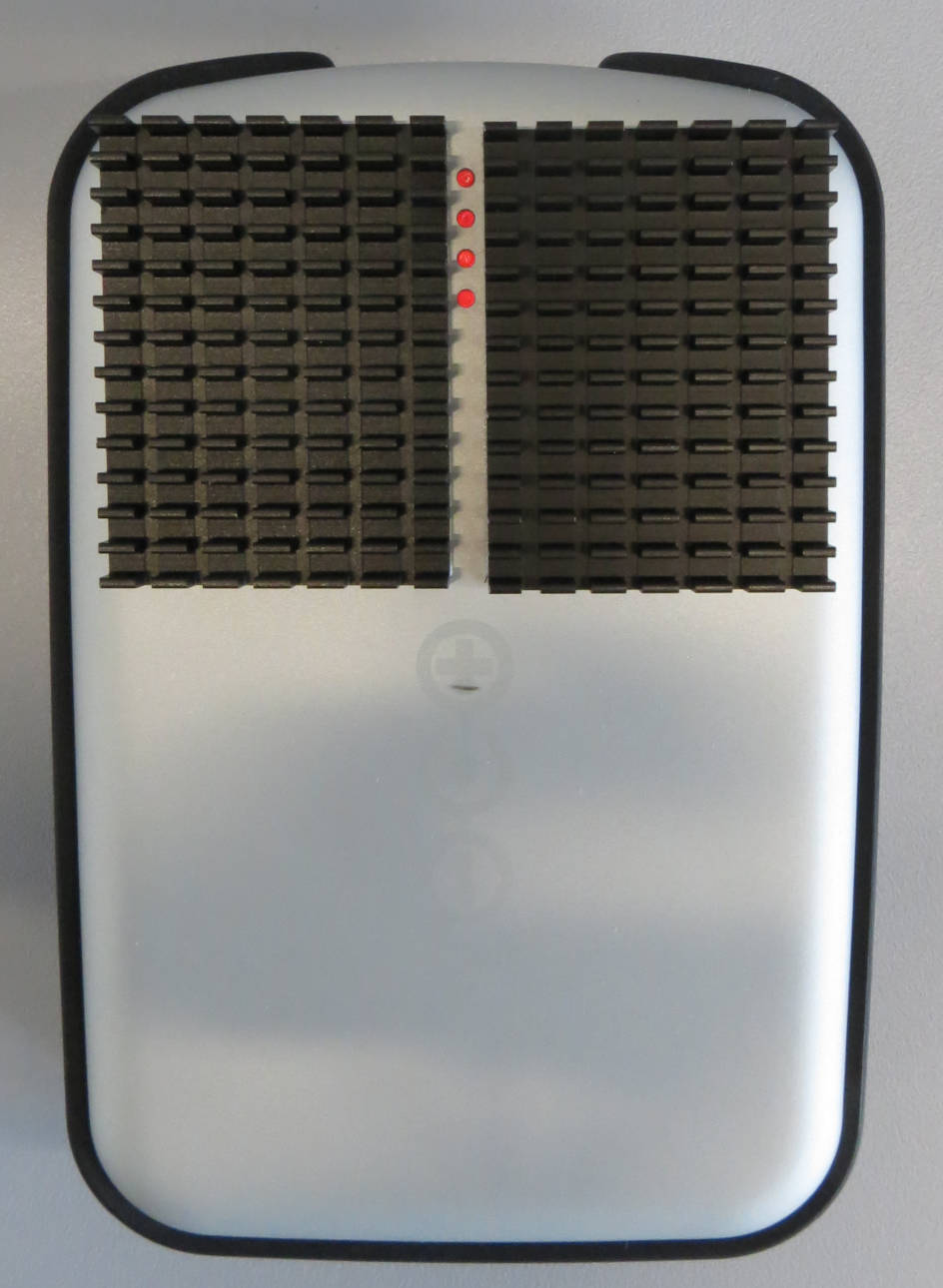
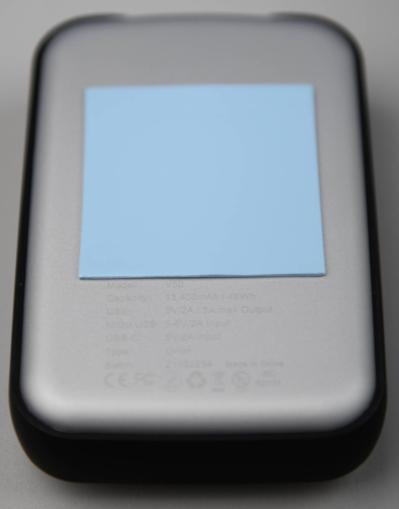
The Voltaic V50 battery has an integrated over temperature protection, which means that it will stop charging at 45 °C. To improve the heat dissipation, you can attach two heatsinks to the top of the battery and stick the battery to the mounting plate with a thermal pad. This step is recommended if your camera trap will be exposed to high temperatures in summer.
Plug the micro USB adapter into the male port of the solar panel extension cable and connect it to the battery.

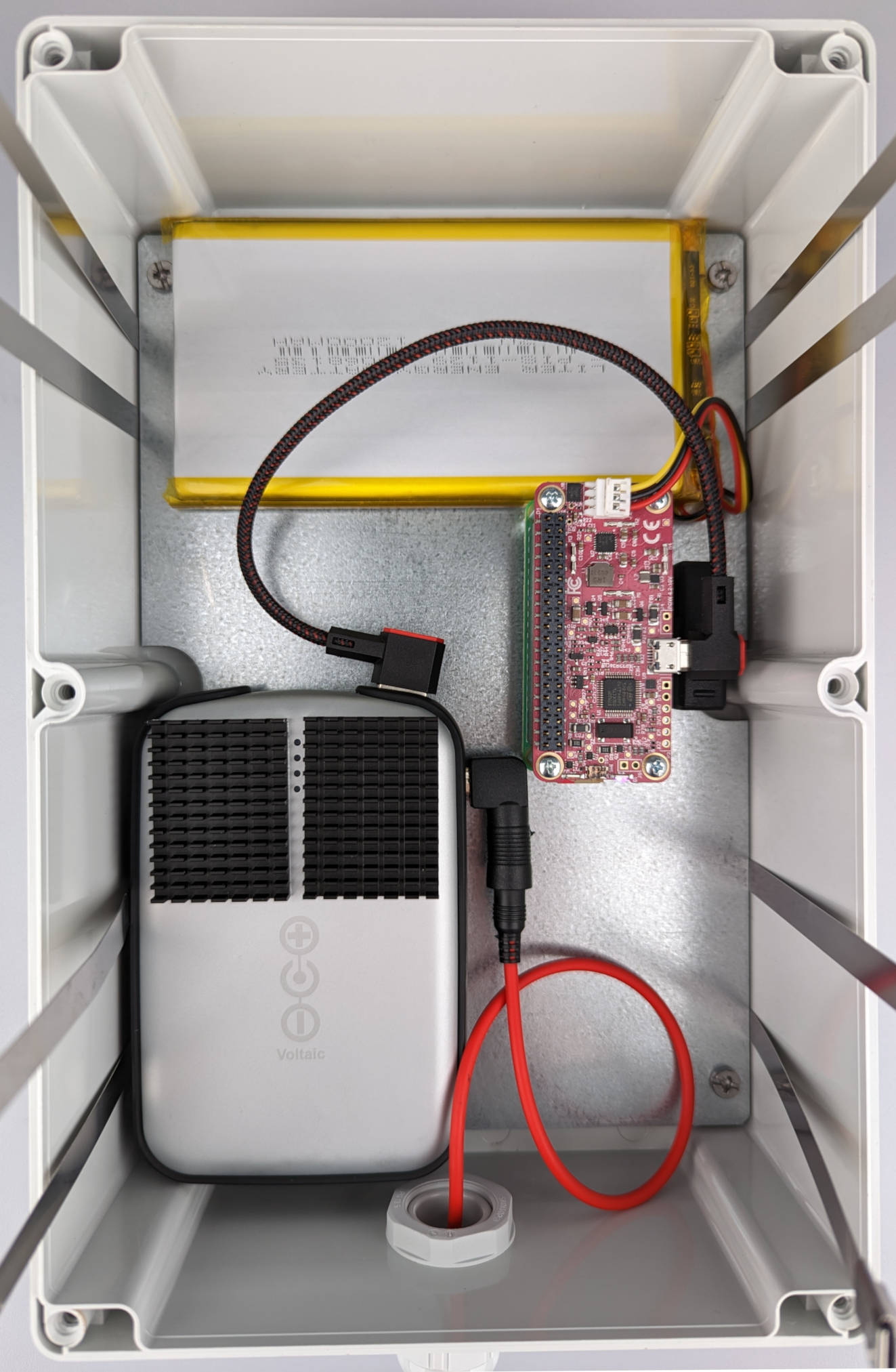
Now you can integrate the battery into the enclosure and put the female end of the extension cable through the opened cable gland. While the two cable ties should be sufficient to keep the battery in place even if you are not using the thermal pad, you could use two small pieces of double-sided tape or velcro strips to more securely attach the batteries to the mounting plate.
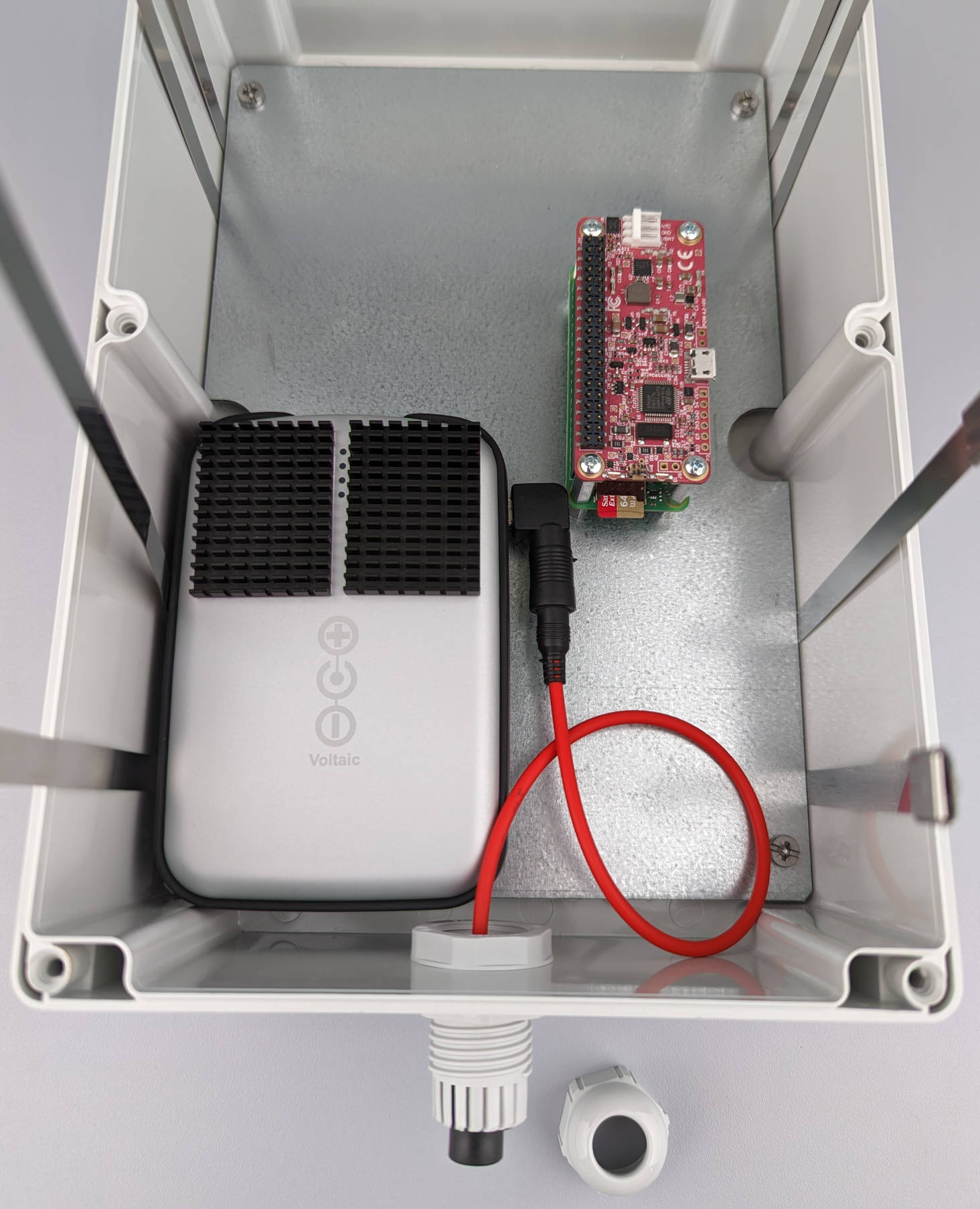
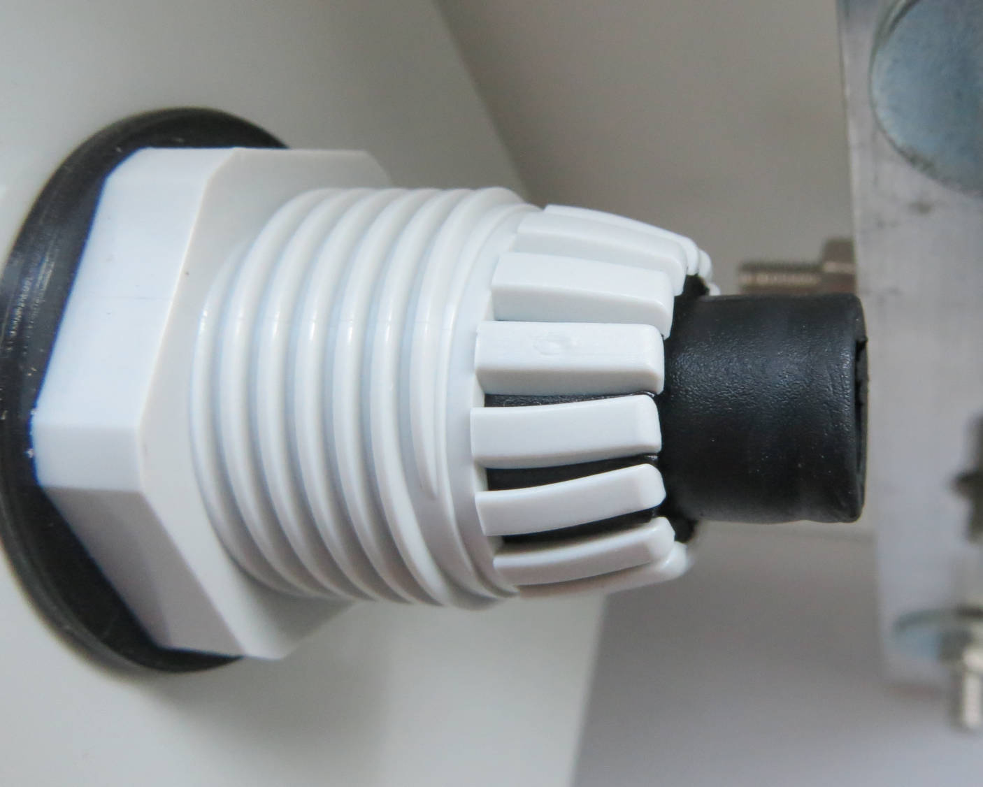
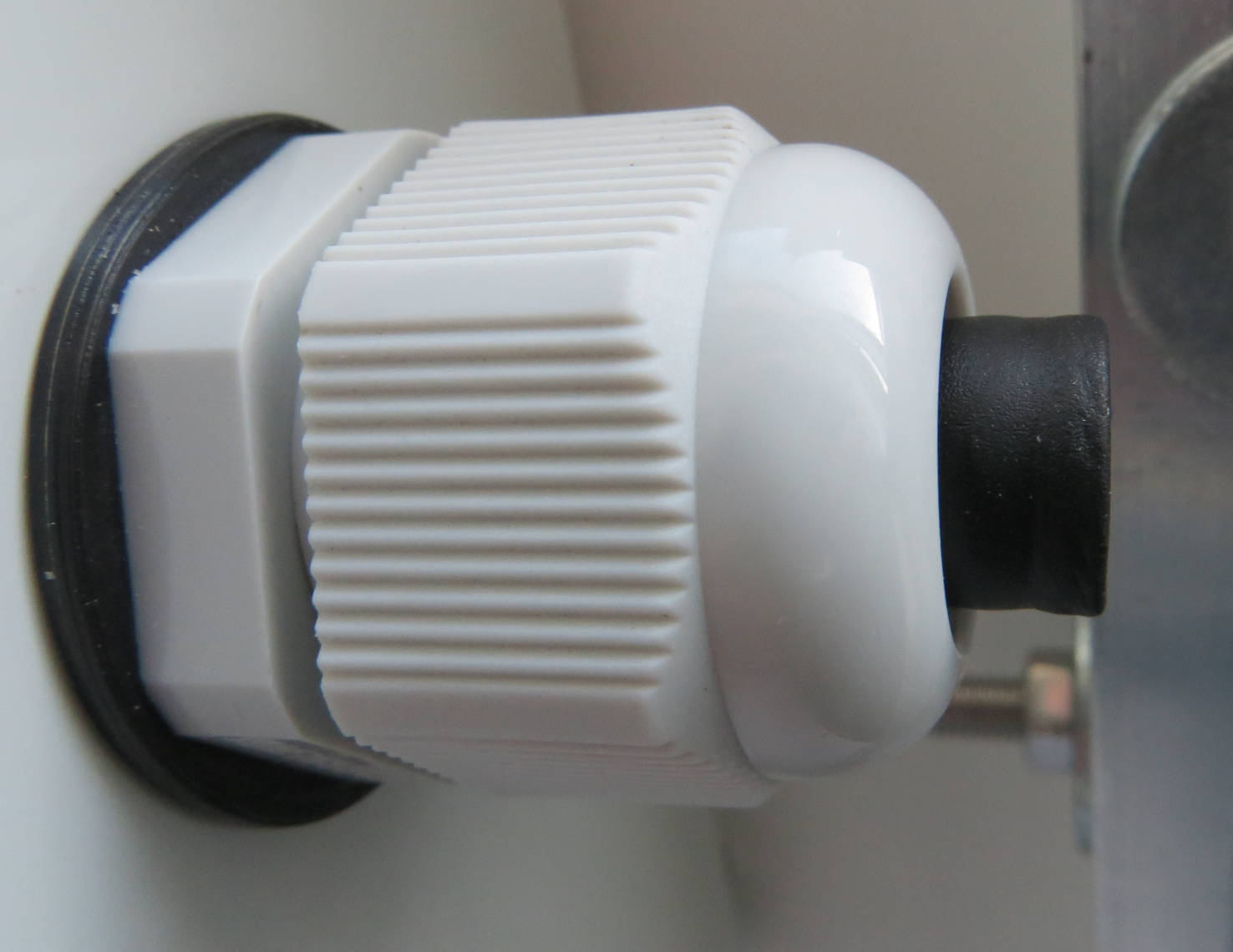
Push the female port of the solar panel extension cable through the cable gland until the overmold is approximately ⅔ of the way in. Tighten the sealing nut properly to make sure that the enclosure will be waterproof.
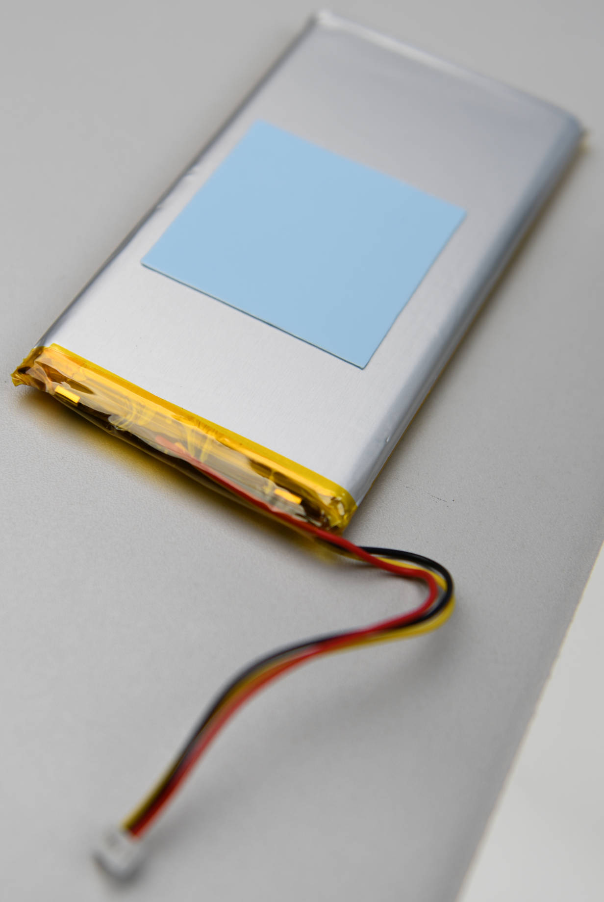
Optionally, you can stick the PiJuice battery to the mounting plate with the second thermal pad or some double-sided tape/velcro strips.
Now that all of the hardware components are integrated into the enclosure, we will connect everything in the next step before tightening the cable ties.
Connecting everything
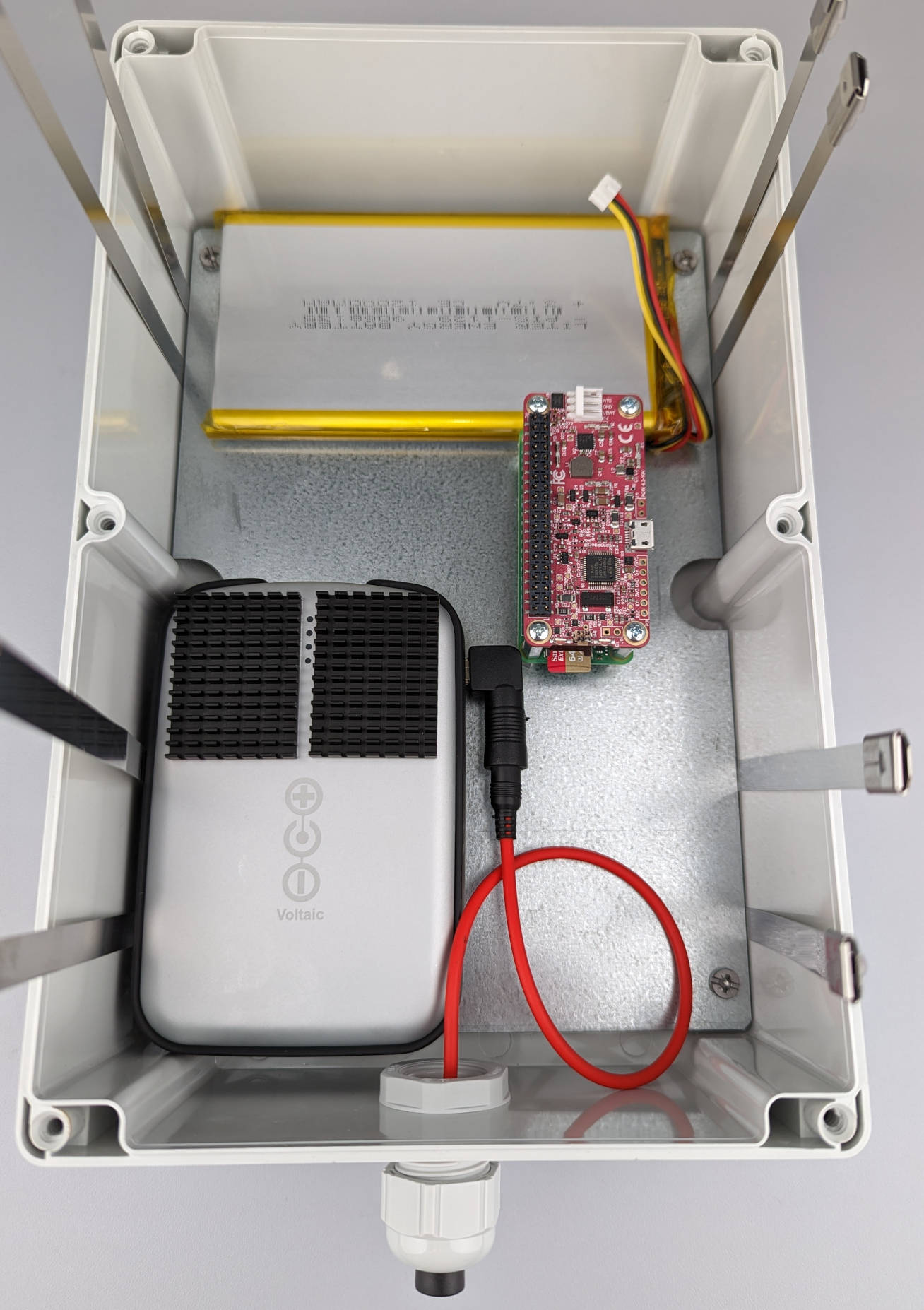
Plug the angled micro USB to USB A adapter into the micro USB port of the Raspberry Pi Zero 2 W. This adapter is necessary to connect the OAK-1 USB cable.
Connect the PiJuice battery with the PiJuice Zero pHAT. Please make sure that the holes for the connection pins are facing downwards.

In the next step, we will connect the solar panel battery to the PiJuice Zero pHAT with the angled USB A to micro USB cable. Now you could already connect the solarpanel, but if you want to continue with the following steps for mounting the camera trap, it is recommended to connect the solar panel only at the end of the mounting process.
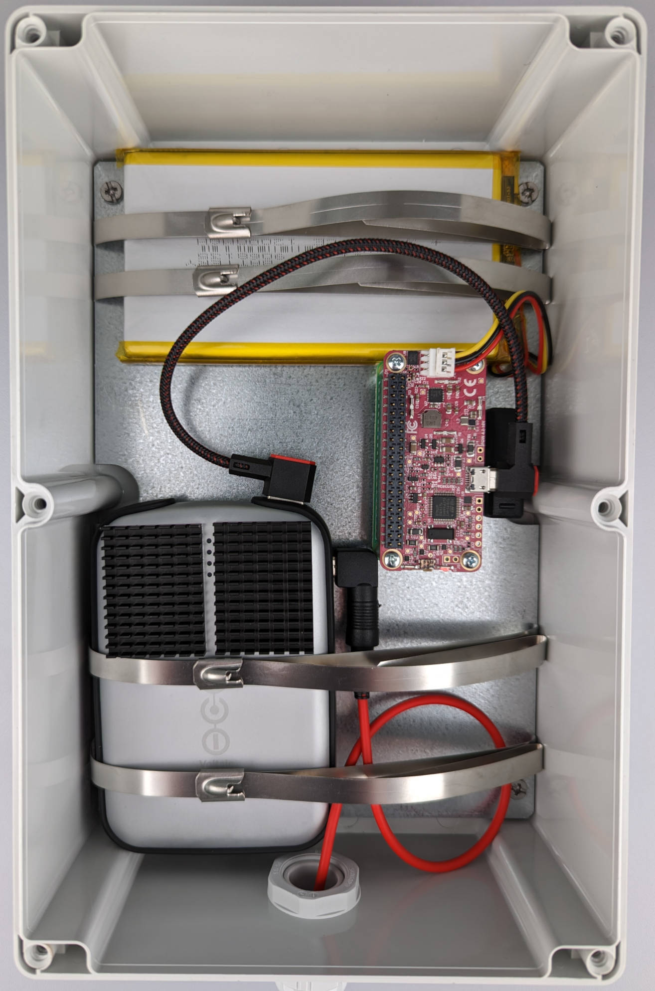
Now that everything is in place, tighten the cable ties to keep the batteries secure, as the enclosure will be turned over for mounting. Cut off or bend the protruding ends after tightening.
In the last step, connect the OAK-1 camera to the micro USB adapter in the Raspberry Pi with the USB 3 Type-A to Type-C cable, which was included in the OAK-1 package.
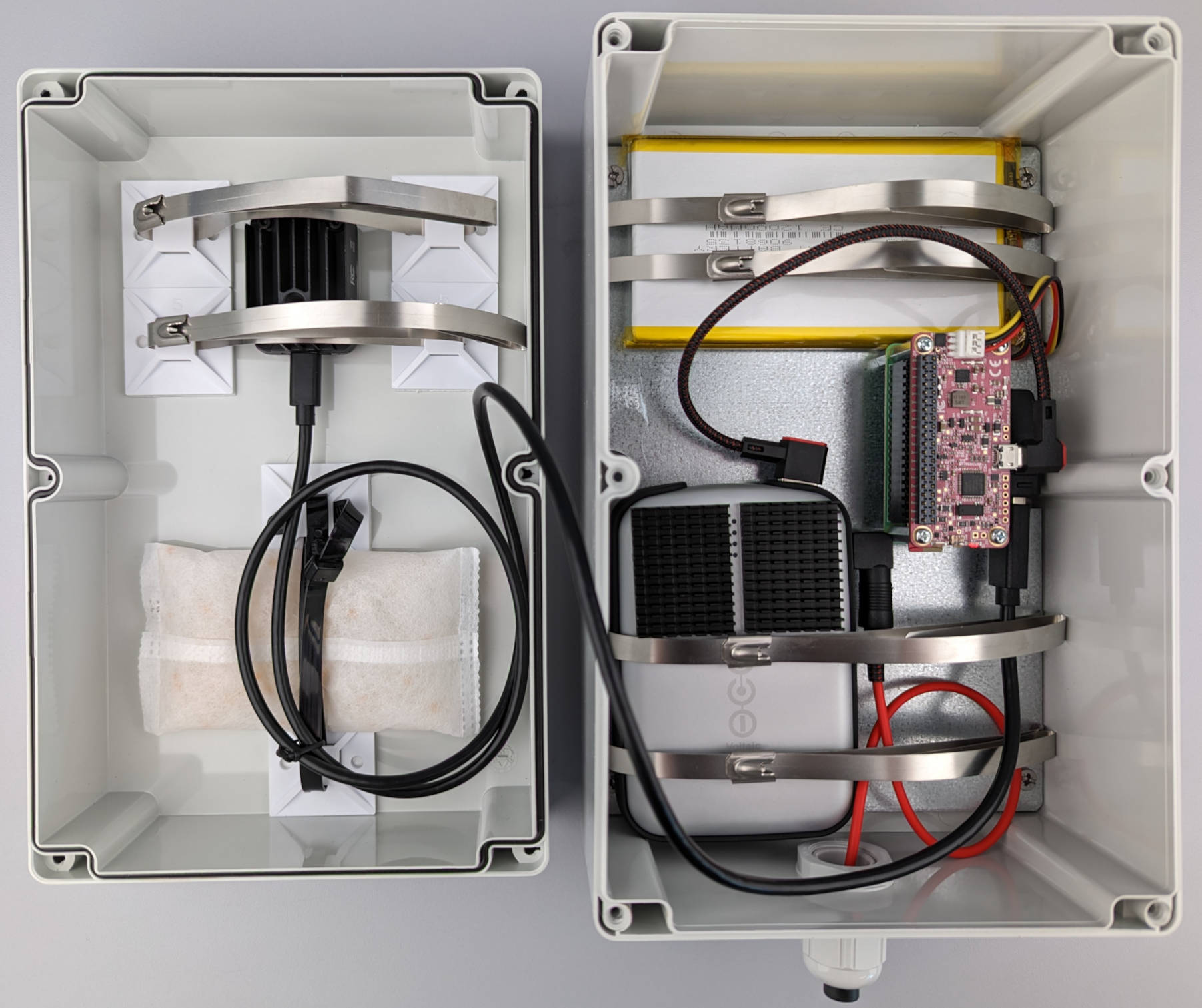
If you are going for the Minimal Setup you are now finished! Don't close the lid yet, as we need to set up the software in the next steps. If you want to build the Full Setup, continue with the next step for mounting of the camera trap and flower platform.